The inner workings of the Reflex were reasonably well documented at the time of its release. Ansco released photos of the camera parts and assemblies to photography magazines, along with details of how the camera was assembled.
The camera itself is relatively simple. An aluminum casting makes up the main part of the body. The casting itself is lightweight.
Four brass guides, two on each side, are pressed and screwed into each side. A steel guide, attached to each side of the lens panel, glides along the V grooves of the brass guides. The bearings are greased, a grease that remains in good condition 70 years after it was applied. A cam follower pin, on both sides, engages with the cam in the focusing knob on both sides. Springs on the right side help with the “return” part of focusing.
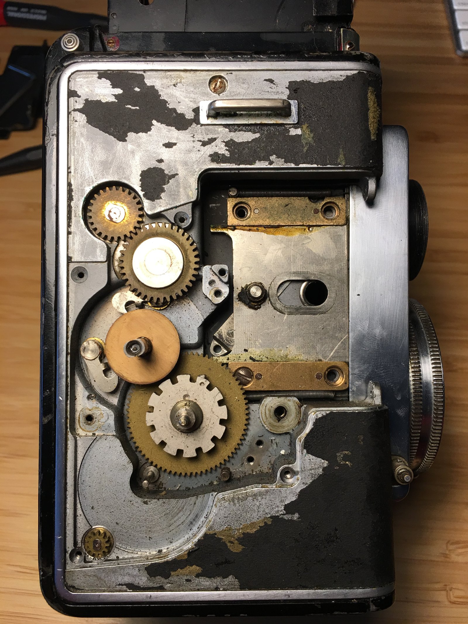
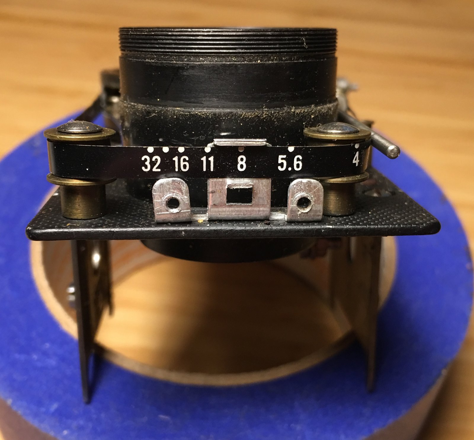
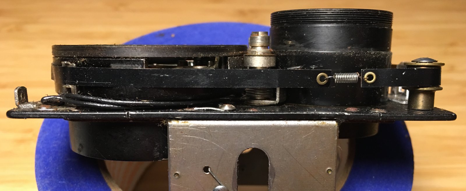
Right side of the Ansco Reflex with side panels, focusing knob and several gears of the film counter mechanism removed.Top view of the aperture tape.Side view of the aperture tape.
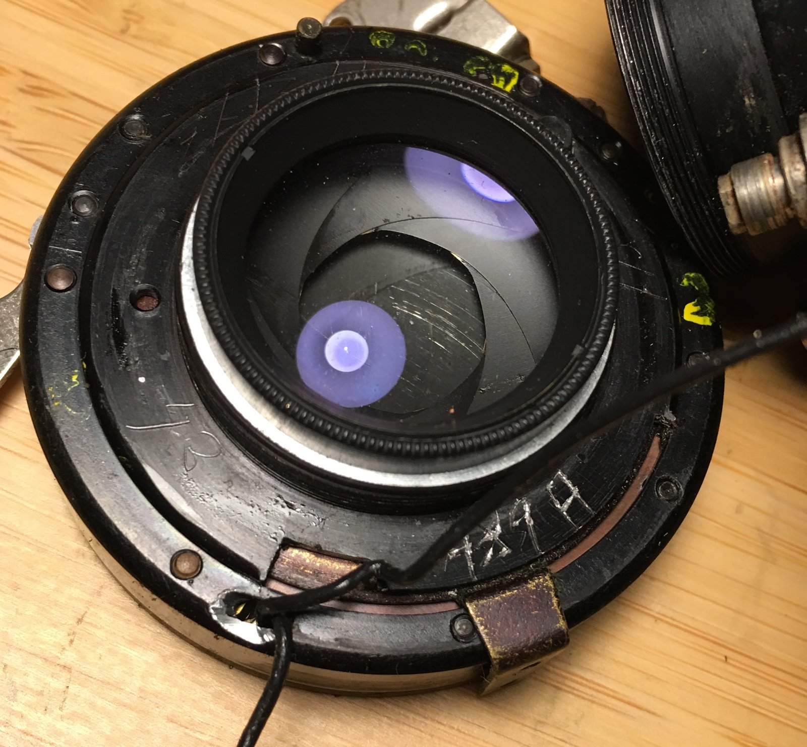
A Wollensak lens and shutter assembly are mounted on the lens panel. A thin metal belt, attached to the focus lever, transmits the aperture value to the window at the top.
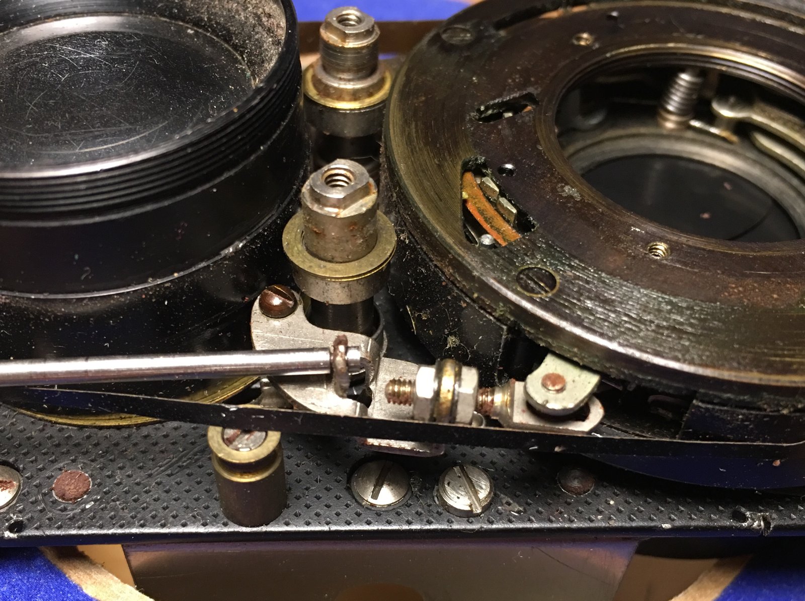
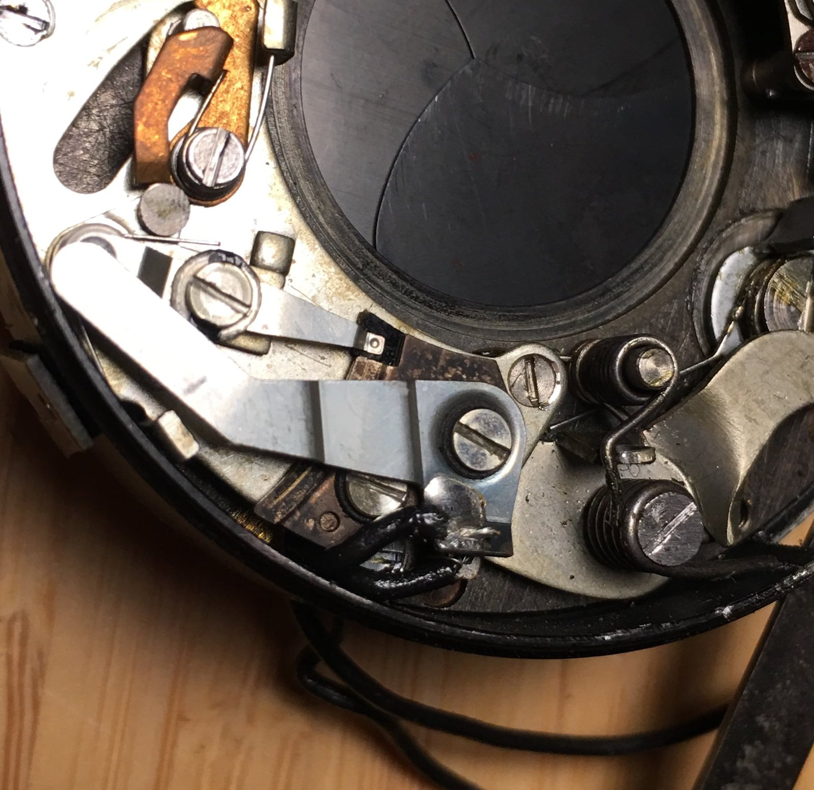
The adjustable linkage connecting the Wollensak shutter release to the lever and the flash post.
The shutter release mechanism is a little complicated, one that required fine tuning at the factory. The notorious interlock release, on the side of the camera, could do nothing to remedy a jam in the lens shutter itself. Such a jam would render a camera inoperable, like the example in these photos.
This particular Reflex started life as a type 1. Standoffs on the left and right side of the lens acted as guides for the shutter tape. The standoff on the right was drilled out for the flash connector standoff.
Close up of the flash sync post.
A wire, fed into the shutter, is soldered to the release post. Another wire is screwed to the baseplate of the lens panel, providing a ground for the flash sync.
The ground connection for the flash sync.
The most tell-tale indicator of this retrofit is the machining of the shutter assembly. It’s clear that the opening for the flash sync is not original: it appears to have been ground into the case.
Back of the Wollensak shutter/lens assembly. You can see where a worker ground a hole for the flash sync wires.
Inside the shutter, the sync connections are factory original parts. The Wollensak Rapax was designed with flash sync; apparently it was up to the camera manufacturer to decide if they’d use it.
Close up of the flash sync contacts inside the shutter.
What is clear, however, is how much work went into retrofitting flash sync to existing type 1 cameras. The side panels, along with the overlaying leather covering, had to be removed to gain the access necessary to remove the lens panel from the camera.
Upgrading a type 1 with flash sync requires removing the stamped cover and removing the lens unit from the lens panel. It is a near complete disassembly of the lens mechanism. At $24.50, the cost at the time, owners received quite a good deal.
Left side of the Reflex showing the cast body and panel under the leather.
Front of the Reflex with the cocking and shutter levers removed, linking gear and aperture gear around viewing lens removed.
Serial number on bottom of lens panel. The 'S' may have been a way of indicating that this model had been upgraded with a flash sync.
Close up of the wind lever, counter and reset lever.
Close up of the right side showing the film counter, winding arm and reset lever.
Close up exterior view of the flash sync modification.
Close up view of left side and focusing knob. The cover is removed from the knob, revealing the screw that holds it on. Users could remove the knob if they desired.
Depth of field chart on the back of a Reflex.
Right side showing focus wheel and brass slide bearings.
Right side with wind lever and counter panel removed.
Right side of the Reflex showing winding and film counter gearing.
Right side showing film counter and winding gears.
Right side with focus wheel and counter gears/wheel removed. The gear with the large, squared gaps is coupled to the counter wheel.
Right side with almost all gears removed.
The mirror for the viewing lens/ground glass. The mirror is mounted with clips and glue to a backing plate. The entire backing plate can be removed from the camera. The pairs of nuts at the top and bottom of the photo are the camera strap hangers.
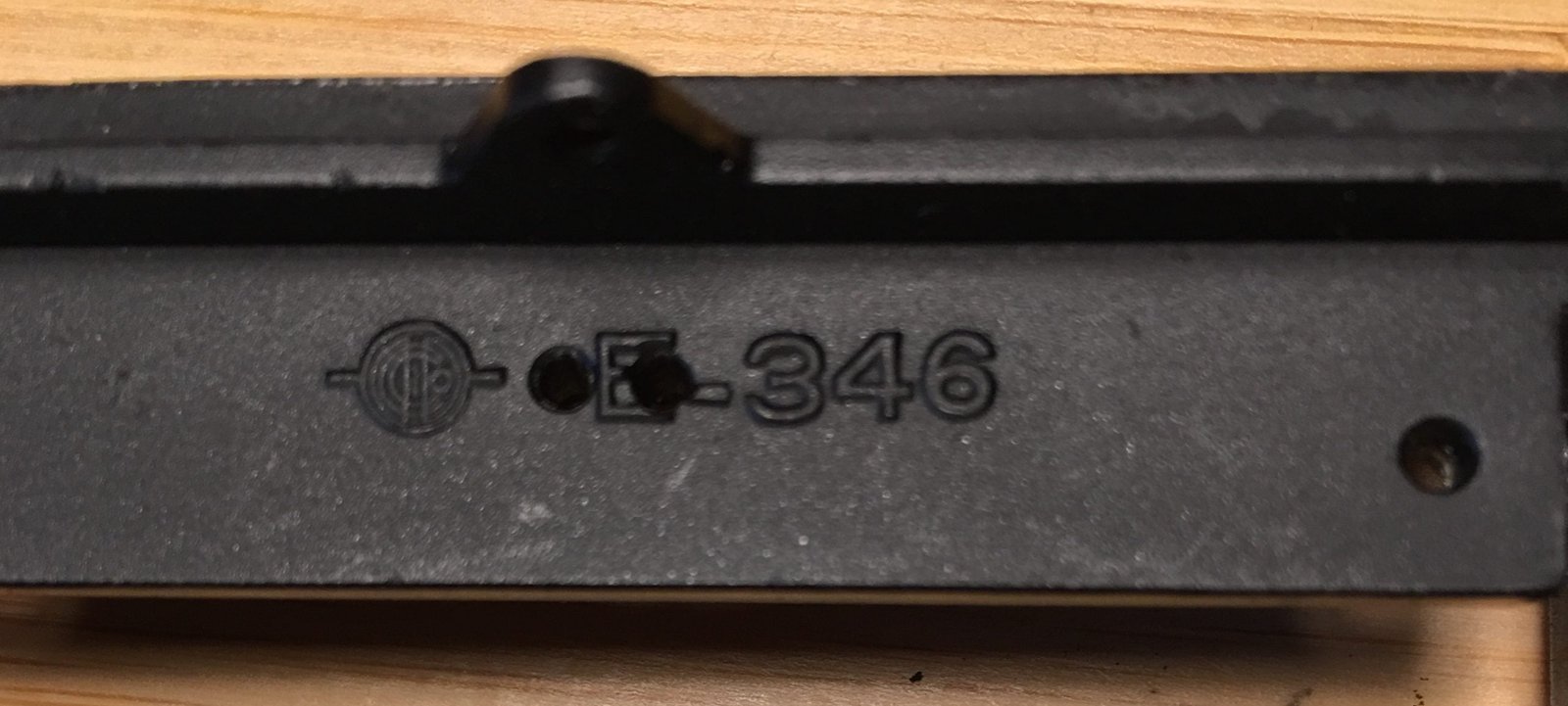
Close up of rear mounting panel for the finder hood and back latch, showing the part number and an unknown logo.
Right side of the lens panel. The springs provide some resistance when focusing and assist in pulling the panel in toward the body.
Inside view of left side of lens panel assembly.
Right side of the lens panel assembly. The rod connecting the focusing wheels goes through the oval holes. The partial pin and lever on the right engage the cam in the focusing knob and move the panel in and out as the knob is turned.
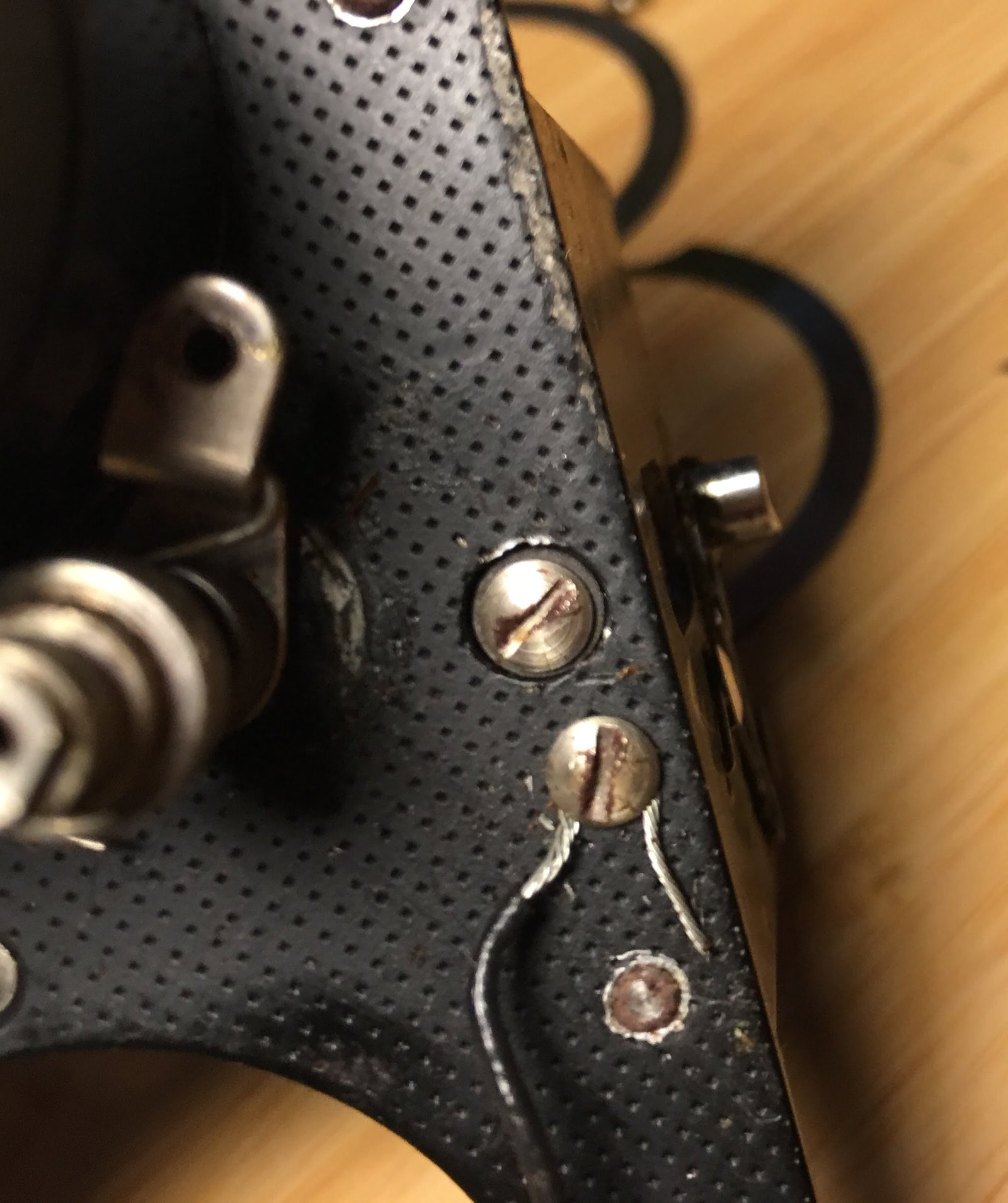
Back of the lens panel. On the lower left, you can see the original rivet for the aperture tape guide. On the right, you can see the replacement rivet (the original was drilled out) for the new flash sync post.
The adjustable linkage connecting the Wollensak shutter release to the lever and the flash post.
Left side of lens panel showing the aperture tape. The spring is used to maintain tension. The Rolleiflex T used a similar tape to show EV values.
Aperture lens tape, viewed from the top.
Lens panel with front lens elements and cover removed.
Close up of aperture tape guide and flash sync post.
Ground screw connection for the flash sync.
Back of the Wollensak shutter/lens assembly. You can see where a worker ground a hole for the flash sync wires.
Flash sync connections in side the Wollensak shutter.
Close up of the flash post mount.
Close up of the flash sync post and aperture band guide. The flash sync post is riveted through the original hole the aperture band guide was mounted via.
Back side of the lens panel, showing the rivet that holds the flash sync post.
Guide post for the aperture tape.
"For Best Results" decal on the inside of the back cover, placed over a slightly different design decal.
Inside bottom of the back panel, showing the stamped numbers. 7-47 may be a manufacturing or inspection date.


 for the new flash sync post.")


